CNC Inspection Repair Guides Checklist: Shop-Floor Workflow
- Document spindle runout and bearing noise before.
- Use a dial indicator to check toolholder taper contact.
- Verify preload and alignment after reassembly with a test.
I’ve been on the shop floor for fifteen years, and I’ve learned that a solid checklist saves more than time—it saves machines. When a CNC comes in for repair, the first thing I do is grab my clipboard and a fresh inspection sheet. This guide walks you through the practical sequence I use, from intake to final sign-off, so you can catch issues early and avoid repeat failures. Every step here comes from real jobs in Ohio shops where we follow ANSI standards for spindle and toolholder checks. Let’s get into it.
Intake Assessment and Initial Documentation
Gathering Operator Reports and Machine History
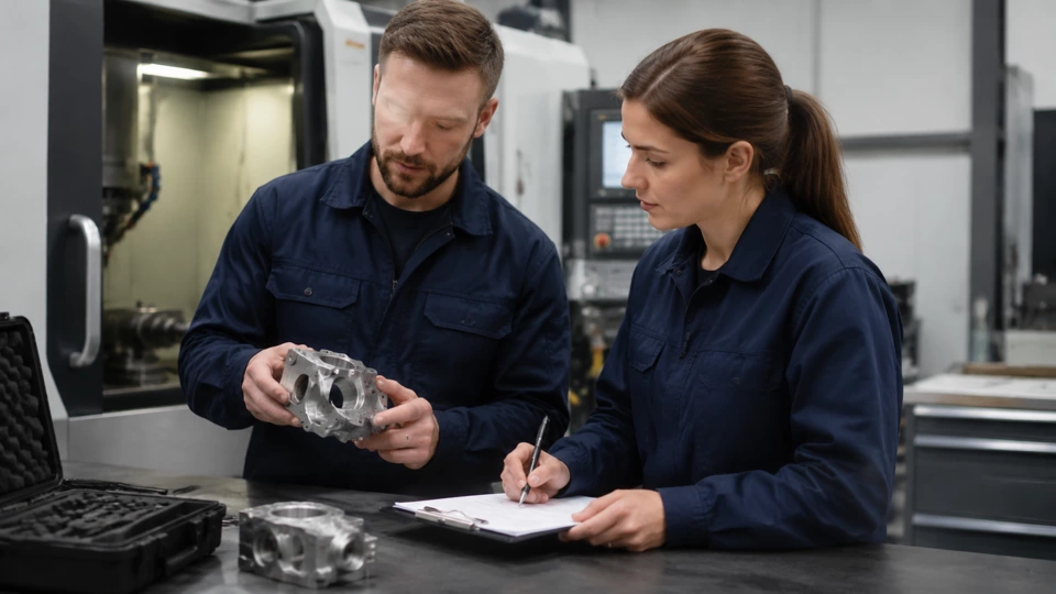
Before I touch a single bolt, I sit down with the operator who ran the machine last. I ask about unusual sounds, vibration patterns, and any recent crashes or tool changes. This conversation often reveals more than any sensor reading. I also pull the maintenance log to see when the last spindle alignment was done and whether any bearing replacements were recorded. In one case, an operator mentioned a high-pitched squeal during a finishing pass—that turned out to be a failing front bearing that we caught before it seized. Documenting these details on the intake form gives me a baseline for comparison later.
Next, I perform a quick visual inspection of the machine’s exterior and coolant system. I look for leaks, damaged way covers, and any signs of coolant contamination in the spindle area. I also check the tool changer for chips or debris that could affect toolholder seating. This initial walk-around takes about fifteen minutes but often highlights issues that the operator didn’t notice. For example, a small puddle of oil under the spindle nose might indicate a seal failure that needs attention during the repair. I record all findings on the intake checklist, noting the machine’s serial number, hours on the spindle, and the date of the last preventive maintenance.
Finally, I take a few critical measurements before any disassembly. Using a dial indicator on the spindle taper, I measure runout at the nose and at a point three inches out. I also check the drawbar force with a calibrated gauge if available. These numbers become the “before” data that I’ll compare to the “after” measurements once the repair is complete. In Ohio, we often use ANSI B5.50 for spindle nose tolerances, so I note whether the initial readings fall within spec. If they don’t, I know the repair will need to address alignment or bearing issues. This step is non-negotiable—it protects both the technician and the customer by providing objective proof of the machine’s condition at intake.
Disassembly and Component Inspection
Step-by-Step Takedown with Parts Organization
Once the intake paperwork is done, I move the machine to a clean bay and start disassembly. I always label every part and fastener with a marker and store them in segmented trays. For a typical spindle repair, I remove the toolholder, then the drawbar assembly, and finally the spindle cartridge. I take photos at each stage, especially of bearing orientations and shim placements. This documentation is invaluable when reassembling, because it shows exactly how the original components were arranged. I’ve seen too many rebuilds fail because a technician guessed at the preload shim stack and ended up with excessive end play.
With the spindle cartridge on the bench, I clean all components with a solvent and inspect them under good lighting. I look for brinelling on bearing races, discoloration from overheating, and any cracks in the spindle shaft. I also check the toolholder taper for wear or galling—a damaged taper can cause runout issues even if the bearings are perfect. Using a bore gauge, I measure the spindle bore diameter at several points to check for ovality. If the bore is out of round by more than 0.0002 inches, I recommend replacing the spindle cartridge. In one job, I found a 0.0005-inch ovality that was causing inconsistent toolholder seating; after replacing the cartridge, the machine’s finish improved dramatically.
After inspecting the spindle, I turn to the drawbar and clamping mechanism. I check the drawbar’s threads for wear and measure its stroke length. I also inspect the collet or chuck for cracks and measure its gripping force with a pull-test gauge. If the drawbar force is below the manufacturer’s spec, the toolholder can slip during heavy cuts, leading to poor surface finish or even tool ejection. I record all measurements on the inspection sheet and compare them to the machine’s original specifications. This thorough component inspection ensures that no hidden defects will cause a repeat failure after the repair is complete.
Bearing Replacement and Preload Setup
Selecting Bearings and Setting Preload Correctly
When the old bearings are out, I clean the bearing seats and measure the housing bore and shaft journal diameters. I use a micrometer and bore gauge to ensure they are within tolerance. If the housing is worn, I may need to use a Loctite bearing mount or replace the housing altogether. I always install new bearings from a reputable manufacturer, matching the original ABEC class or better. For high-speed spindles, I prefer angular contact bearings with a light preload. I apply a thin film of oil to the bearing seats and press the bearings onto the shaft using a hydraulic press with a proper fixture—never hammer them on.
Setting bearing preload is one of the most critical steps. I use a preload fixture that applies a known axial load while I measure the bearing’s deflection. For a typical spindle, I aim for a preload that gives a deflection of 0.0002 to 0.0004 inches under a 50-pound load. I adjust the shim stack until I achieve the target deflection. If the preload is too light, the spindle will have excessive runout and vibration; too heavy, and the bearings will overheat and fail prematurely. I’ve seen shops skip this step and just tighten the nut to a torque value, but that method is unreliable because it doesn’t account for variations in bearing stiffness. Taking the time to measure preload pays off in spindle life and accuracy.
After setting the preload, I install the spindle cartridge back into the housing, being careful not to damage the bearings. I torque the retaining nuts to the manufacturer’s specification and check the spindle rotation by hand—it should turn smoothly with no binding. I then install the drawbar and toolholder, and perform a preliminary runout check with a dial indicator on the spindle taper. At this stage, I expect to see runout under 0.0002 inches at the nose. If it’s higher, I may need to adjust the preload setup or check for contamination in the taper. This step ensures that the alignment check is within acceptable limits before moving on to the final tests.
Final Assembly and final measurement
Reassembly, Alignment, and Final Measurement
With the spindle back in the machine, I reconnect all coolant and air lines, and install the tool changer if it was removed. I then power up the machine and run a warm-up cycle at low RPM for about 30 minutes. This allows the bearings to reach operating temperature and any thermal expansion to stabilize. During warm-up, I listen for unusual noises and monitor the spindle temperature with an infrared thermometer. A temperature rise of more than 20°C above ambient could indicate excessive preload or a lubrication issue. I also check for vibration using a handheld accelerometer; readings above 0.1 in/sec suggest a problem that needs investigation.
After warm-up, I perform the final runout inspection. I mount a precision test bar in the spindle and measure runout at the nose and at 12 inches from the nose using a dial indicator. The ANSI standard for a CAT40 spindle is 0.0002 inches at the nose and 0.0005 inches at 12 inches. I record these values on the inspection sheet and compare them to the intake measurements. If the runout is within spec, I proceed to a test cut on a piece of aluminum. I take a light finish pass and measure the surface finish with a profilometer. A good finish indicates that the alignment check and preload setup are correct. I also check the toolholder pullback force with a drawbar force gauge to ensure it meets the manufacturer’s specification.
Finally, I run a series of acceptance tests: a taper contact test using bluing, a thermal growth test, and a vibration analysis at various RPMs. I document all results on the final inspection report. If any test fails, I go back and adjust the preload or alignment as needed. Only when all tests pass do I consider the repair complete. This rigorous final inspection ensures that the machine will perform reliably in production. I’ve seen too many repairs that looked good on paper but failed on the floor because the technician skipped the final measurement. Taking the extra hour to verify everything saves days of downtime later.
Documentation and Release for Production
Completing the Checklist and Obtaining Sign-Off
Once the machine passes all tests, I fill out the final section of the checklist. I record the final runout values, preload setup settings, and any adjustments made during the repair. I also note the date, technician name, and the machine’s new hours. I attach the intake photos and the final test data to the report. This documentation becomes part of the machine’s permanent record and is useful for future maintenance. In Ohio, many shops require a signed acceptance form before the machine goes back to production, so I make sure the operator or supervisor signs off on the work.
I also create a summary of the repair that highlights any unusual findings, such as a worn taper or a damaged drawbar. This summary helps the next technician who works on the machine understand its history. I store the checklist in a binder organized by machine number, and I also scan it into the digital maintenance system. Having a complete record allows us to track trends over time—for example, if a particular machine needs frequent bearing replacements, we might investigate the coolant system or the operator’s practices. Documentation is not just paperwork; it’s a tool for continuous improvement.
Before releasing the machine, I run a final visual check of the work area to ensure no tools or rags are left inside. I also verify that all safety guards are in place and that the coolant levels are correct. I then start the machine and let it run through a short automatic cycle to confirm that the tool changer and coolant system function properly. Once everything looks good, I hand the keys back to the operator and explain what was done and what to watch for in the first few shifts. A clear handoff prevents misunderstandings and builds trust with the production team.
Author Note
Expert context
This guide reflects my hands-on experience repairing CNC spindles and toolholders in shops across Ohio. Every machine is different, but the workflow I’ve outlined here has helped me consistently deliver reliable repairs. Remember that this content is informational and not a substitute for your own judgment or manufacturer guidelines. If you have questions about a specific machine, consult the manual or a qualified technician. I hope these practical field notes help you keep your spindles turning smoothly. — David Hartley, CNC Maintenance Advisor
| Stage | Technician action | Acceptance sign |
|---|---|---|
| Initial review | Documented shop observation | Controlled next step |
For a related shop-floor reference, compare these checks with CNC inspection checklist before changing the maintenance plan.